


Like it? Share it!


Relay Module for GPS
Relay module for solenoid activated shutoffs
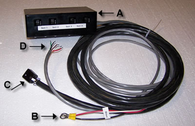
- Relay module (circuit breaker for each section)
- Power Cord - connect to battery
- Cable and connector - plug into planter harness
- Signal Cable: Five conductor (18 ga) pigtail (4 ft.) - affix proper plug to accommodate guidance controller.
Two modules are used when 6 or 8 sections are needed.
Module dimensions are 7.6" x 4.3" x 2.3"
Relay pin setting |
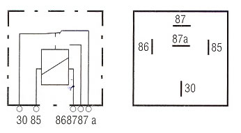 |
| 85 - guidance system ground |
| 86 - guidance system signal |
| 30 - shutoff unit power from battery |
| 87 - power to planter unit - planter logic |
| 87a - power to planter unit - sprayer logic |
| Signal Cable Color Code | |
| Black | Ground or Power |
| Red Wire | Section 1 |
| White | Section 2 |
| Green | Section 3 |
| Brown | Section 4 |
| Note: To affix proper plug to Signal Cable 'D' is additional charge |
System Check - GPS
Relay Module Signal Retrieving Cable
Standard 6 pin WeatherPak connector

Systems with the standard 6 pin WeatherPak connector on the Signal Retrieving Cable of Relay Module can test the Slectro portion of the shutoff via these steps:
1) Relay module connected to 12V battery, tractor hooked to planter.
2) Find WeatherPak connector of signal retrieving cable of relay module (May have two).
3) Supply 12V DC power to pins A and B to activate section 1.
4) Supply 12V DC power to pins A and C to activate section 2.
5) Supply 12V DC power to pins A and D to activate section 3.
6) Supply 12V DC power to pins A and E to activate section 4.
If all sections respond then Slectro equipment is working properly.
SLECTRO COMPANY
303 Sunset Drive
Beresford, SD 57004
(605) 763-8221
www.slectro.com