


Trouble Shooting
Low Voltage at Solenoid

Systems are designed with a machine ground (note jumper wires to ground lug). Make sure there is ground contact through the planter to the tractor. Mounting brackets may have a paint coat that will insulate contact. No machine ground will cause low voltage at solenoid. Also, check cables and cable connections.
Solenoid not responding when activated
Circuit breaker on control module must be set to closed position.
Inspect all cables and connections assured they are of proper quality and clean.

Investigate by activating the solenoid then go to the solenoid and push plunger all the way in to seated position. If solenoid latches and holds plunger, the probable malfunction is dirty points. If solenoid does not latch and hold plunger, then solenoid needs to be replaced.
To clean the points, remove black cover on terminal end of solenoid.
1) Remove terminal nuts fastening electrical wires to solenoid, remove wires.
2) Remove terminal nuts holding cover to solenoid, hold terminal end of solenoid up.

Remove cover carefully as to not lose parts under cover. When cover is removed the points bar and compression spring will be setting there unattached. Clean points and reinstall the points bar and spring under the black cover. Test solenoid.

Circuit breakers overloading and breaking open
1) Check cable and connections to assure proper quality and clean.
2) Assure that cone spring on solenoid stud is in proper position (not lodged between stud and lever).
3) All moving parts must be free of lodging and/or dragging.
4) Assure proper adjustment:
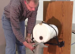
Unit Adjustment
Solenoid plunger must seat in coil to reduce power demand to holding status. When shutoff wheels are engaged, proper adjustment is 1/8 inch or less between gang lever and solenoid plunger while wheel is on a seed dimple of the seed drum. Adjustment is achieved by loosening the four bolts that hold the complete unit and raising or lowering the unit. Do not alter lock nut on solenoid stud.

[Note: When a solenoid is energized the activation coil is charged. When plunger seats the activation coil is shut off and the hold coil maintains plunger position.]
System Check - GPS
Relay Module Signal Retrieving Cable
Standard 6 pin WeatherPak connector

Systems with the standard 6 pin WeatherPak connector on the Signal Retrieving Cable of Relay Module can test the Slectro portion of the shutoff via these steps:
1) Relay module connected to 12V battery, tractor hooked to planter.
2) Find WeatherPak connector of signal retrieving cable of relay module (May have two).
3) Supply 12V DC power to pins A and B to activate section 1.
4) Supply 12V DC power to pins A and C to activate section 2.
5) Supply 12V DC power to pins A and D to activate section 3.
6) Supply 12V DC power to pins A and E to activate section 4.
If all sections respond then Slectro equipment is working properly.